
Case

Application

FAQ
Die Bonder Arm Malfunction?
Case|Die Bonder Arm Malfunction?The Die Bonder, or adhesive bonding machine, is responsible for securing chips onto PCB boards. The upper arm places the PCB material at the designated point, and the dispensing arm applies adhesive to the chip position. Each cycle includes picking and bonding. As technology becomes more advanced and complex, how can we ensure process stability and yield?
Die Bonder (Adhesive Bonding Machine) Operating Principles
The Die Bonder secures chips onto PCB boards, with the upper arm placing the PCB material at a designated position and the dispensing arm applying adhesive to the chip location. Die bonding is a critical step in semiconductor back-end packaging processes. With rapid technological advancements and miniaturization of wafers, bonding processes and standards have become increasingly stringent. Every process step must be flawless, requiring users to have a thorough understanding of the equipment to ensure its reliability and stability.

Monitoring Description
EDGE IIOT Edge IoT / VMS-ML Machine Learning Intelligent Monitoring System
Although the adhesive bonding process involves many components and complex movements, it can be managed through a defined periodic process, such as trend analysis based on current peak variations in the moving axis.
With Edge IoT, multiple machines can be monitored simultaneously, allowing real-time status tracking and trend-based management. Alternatively, machine learning intelligent monitoring can be used to learn the arm's signals and establish learning guidelines.
Measurement Conditions
This case focuses on monitoring the current of the upper arm and dispensing arm of the adhesive bonding machine.
Current Situation
・ Operator to machine ratio: 150 machines/2 operators
・ Maintenance schedule: 2 machines per week
・ Maintenance definition: Machines are maintained in order of use time
・ Inability to accurately identify machine needs
・ Unplanned downtime causes maintenance delays
・ Maintenance schedule causes machines to turn into repair cases
・ No insight into machine conditions before and after maintenance
Improvement Goals
・ Install sensors on the X motor of the upper arm
・ Define normal machine current variations
・ Establish resistance-based current change thresholds
・ Use standard deviation algorithms to detect early anomalies
・ Create maintenance schedules based on machine condition changes
・ Predictive maintenance for axial position tuning
・ Verify machine status before returning to operation
Test Experimental Data - In-house Defined Abnormal Machine PM Before and After Current Detection
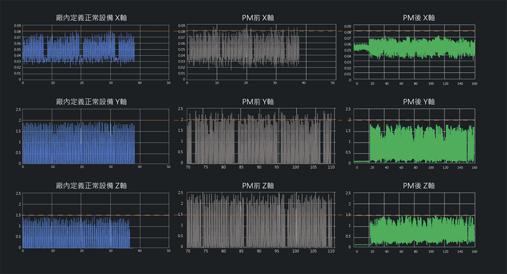
Measurement Conclusions
The current peak values represent the maximum current received by the moving axis to reach the designated position. The software automatically detects and captures movement results and calculates the maximum, average, and standard deviation of current changes in the working area.
Full-speed production standard deviations are lower than reduced-speed production. Automatically capturing peak current values minimizes computational data, allowing better visualization of moving axis stability. Trend analysis of peak values can predict machine changes and schedule maintenance in advance.
Monitoring each movement and current signal ensures uniform power delivery each time. Specific current thresholds can be set for each product type, and all movements are logged for future analysis. Trend data allows for secondary anomaly detection standards.
Die Bonder Quality Monitoring IoT
DB-IoT
Monitor each movement and ensure uniform power delivery.