
Case

Application

FAQ
How to Ensure the Stability of Mask Aligner Exposure Machines?
Case|How to Ensure the Stability of Mask Aligner Exposure Machines?In semiconductor manufacturing, photolithography is used to expose circuits onto wafers using light waves. Any abnormal vibration during the process can easily lead to defective products. How can detection and prevention be effectively implemented?
Mask Aligner Exposure Machines
Mask aligners are key devices used in the production of MEMS, optoelectronics, and large-scale integrated circuits. They can be classified into two types: contact aligners, where the mask directly contacts the wafer during exposure, and projection exposure systems such as steppers and scanners, which use short-wavelength lasers to project images onto the wafer, achieving exposure patterns smaller than the mask itself.

Operating Principle of Mask Aligners
The basic steps for producing integrated circuits include using a mask to remove the protective layer on the wafer surface. The wafer is then immersed in an etchant, which corrodes the exposed areas, forming the circuit. The mask aligner uses ultraviolet excimer lasers to remove the wafer’s protective film through the mask.
A single wafer can produce dozens of integrated circuits. Based on mask aligner design, they can be classified into two types: fixed masks, where the mask and wafer are the same size and remain stationary, and moving masks, where the mask and circuit are of equal size and move with the exposure machine. In the latter case, the mask remains in a fixed position relative to the center of the exposure machine, ensuring higher precision by consistently using the center of the focusing lens. Source: Wikipedia
Solutions and Monitoring Explanation
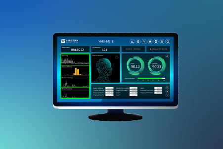
VMS-ML Machine Learning Intelligent Monitoring System
Gude Technology performs multi-axis measurements on the exposure machine's vibration isolation platform to analyze axial changes. The measured vibration data is visualized, converting numerical values into intuitive graphical representations. Combined with operator experience, these visual insights help identify hidden process issues, establish maintenance thresholds, and provide a basis for online monitoring.
The VMS-ML machine learning intelligent monitoring system learns standard operational behavior as a reference for monitoring and diagnosing each motion of the machine. By identifying anomalies or instabilities in specific actions, predictive maintenance can be performed early to prevent unexpected failures.
Measurement Status
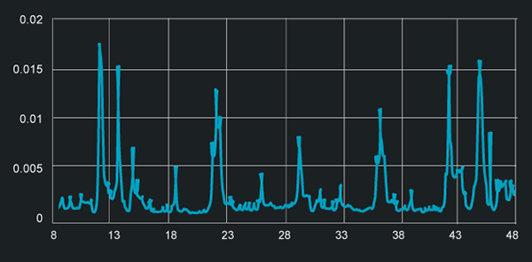
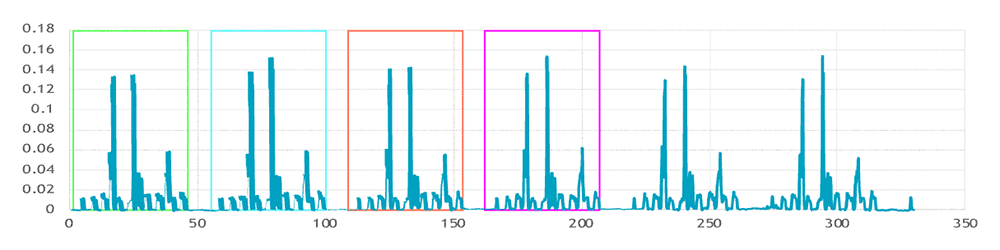
Mask Aligner Vibration Isolation Platform X-Axis Dynamic Signals
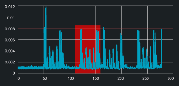
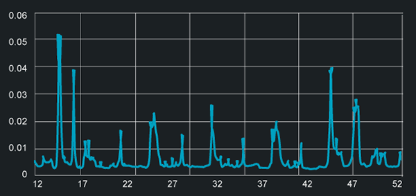
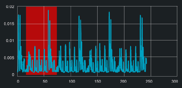
Device A X-Axis
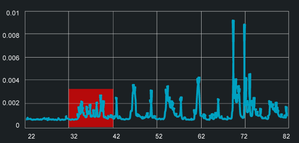
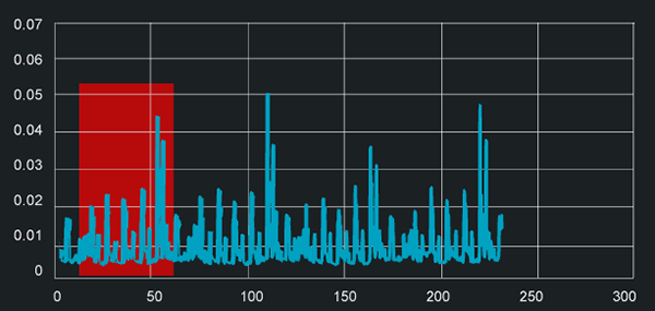
ZOOM IN: Device A X-Axis
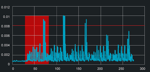
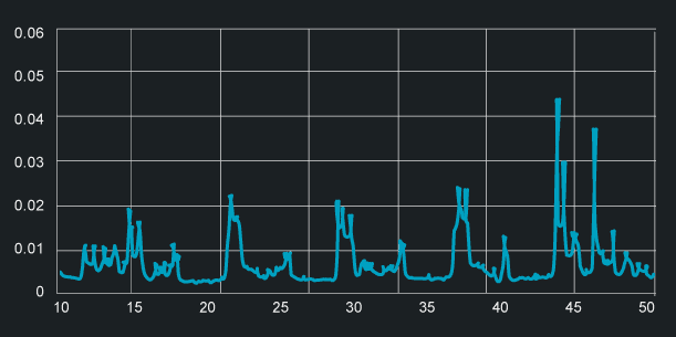
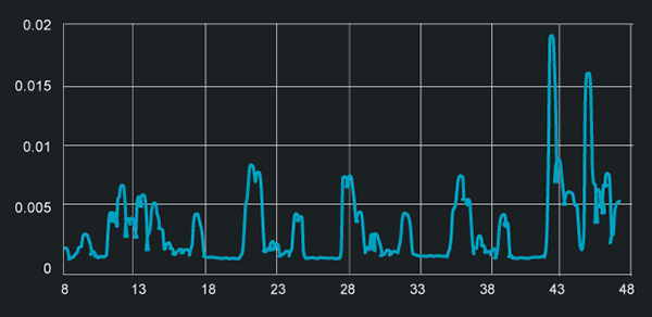
Device B X-Axis
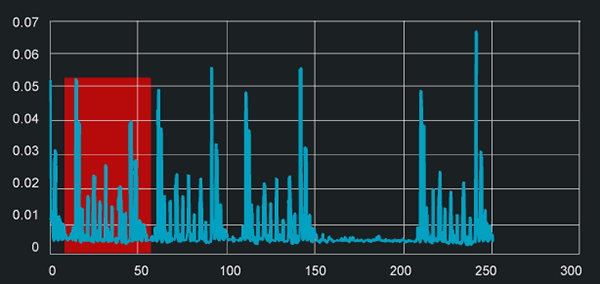
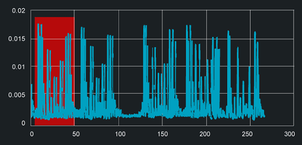
ZOOM IN: Device B X-Axis
During the four exposure cycles, the first movement of Device A's X-axis is larger compared to Device B.
Device B's X-axis vibration in the fourth movement is greater than that of Device A.
Mask Aligner Vibration Isolation Platform Y-Axis Dynamic Signals
Device A Y-Axis
ZOOM IN: Device A Y-Axis
Device B Y-Axis
ZOOM IN: Device B Y-Axis
During the four exposure cycles, the first movement of Device A's Y-axis is larger compared to Device B.
Mask Aligner Vibration Isolation Platform Z-Axis Dynamic Signals
Device A Z-Axis
ZOOM IN: Device A Z-Axis
Device B Z-Axis
ZOOM IN: Device B Z-Axis
Device A Z-Axis (Four Exposure Cycles) - The first movement is larger compared to Device B Z-Axis.
Device B Z-Axis vibration levels in all four movements are greater than those of Device A.
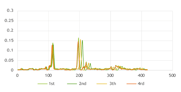
Mask Aligner Robot Dynamic Signal Measurement
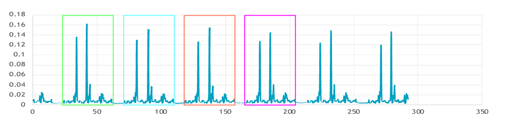
Device A Robot
Device B Robot
The four colors represent the robot's four cyclic operations, with simultaneous movement across multiple axes including X, R, and TH axes.
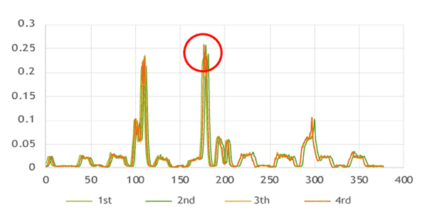
Mask Aligner Robot Dynamic Signal Machine Learning Simulation Management
Device A Robot
Device B Robot
Measurement Conclusion
Device A Robot exhibits lower overall vibration levels compared to Device B Robot. Dynamic signal analysis indicates that all axis movements of Device B Robot are greater than those of Device A. Device B Robot operates at a higher speed than Device A Robot. The only major difference in Device A Robot's performance is observed in the Z-axis movement, while the other axes operate within acceptable conditions.
The VMS-ML Machine Learning Intelligent Monitoring System automatically tracks and identifies machine operations, detecting subtle changes in machine conditions caused by instability, wear, aging, or damage through declining signal similarity. This enables predictive maintenance.
The VMS-PH Dynamic Analyzer focuses on axis damage by identifying pattern differences, pinpointing damaged areas, and providing fine-tuning suggestions. It also accumulates failure signal data to train the VMS-ML system for further predictive capabilities.
VMS-ML Machine Learning Intelligent Monitoring System
Monitor and diagnose individual operations.